Turt'lin in Berlin: Hackaday SAO badge
Early last year I attended the Open Source Hardware Summit in Montreal, Canada. The whole thing was a blast but one of the things I wished I'd done was bring something along to show people. With the theme of Hackaday Berlin 2025 being small SAO badges that could attach to the main conference badge, I figured it would be a good small project to start out with.
There were three main criteria I decided on for the badge:
1. It had to work as an SAO badge-so standard SAO connector plus the whole board could be powered via 3.3V with no crazy current draw.
2. It had to look cool. Since I can’t compete with the absurd things people have built, I may as well get points for aesthetics.
3. It had to do something slightly more complex than just power straight into LED’s. Nothing crazy.[[1]]
Later on in the process I also added a few sub criteria to the list:
- Could be powered without the SAO connection
- Could be worn separately without the conference badge
- Could be assembled and programmed quickly and without too much effort
[[1]]: If you make it to the end of this post, you’ll realise that “slightly more complex than just power straight into LED’s” is probably overstating the final product.
Criteria 2 was pretty easy. I wanted something similar to the EMF-Explorer badge I made in Canada – essentially some cool art with some LED’s shining through the PCB. I’d always been a fan of the late great Sir Terry Pratchett’s Discworld series of books and for Christmas my dad had bought me a copy of Paul Kidby’s Discworld art book[[2]]. After some Googling, I decided there was a gap in the market for a Discworld themed badge.
[[2]]: And if none of those words mean anything to you, I suggest you immediately jump on your book-buying platform of choice and correct that.
Rincewind and Granny Weatherwax both seemed like good candidates but didn’t have any obvious reason for parts of them to be lighting up. For a while I was considering Death, arguably the second most iconic piece of Discworld art, which would have relatively simple to do: white silkscreen on a black board and blue LED’s lighting up the eyes. For various reasons[[3]] I decided against this and went with the most iconic part of Discworld, great A’tuin.
[[3]]: “What’s this?” “It’s a tribute to the late Terry Pratchett”. “Ahh right, what’s it meant to be then?” “It’s the literal embodiment of death”.
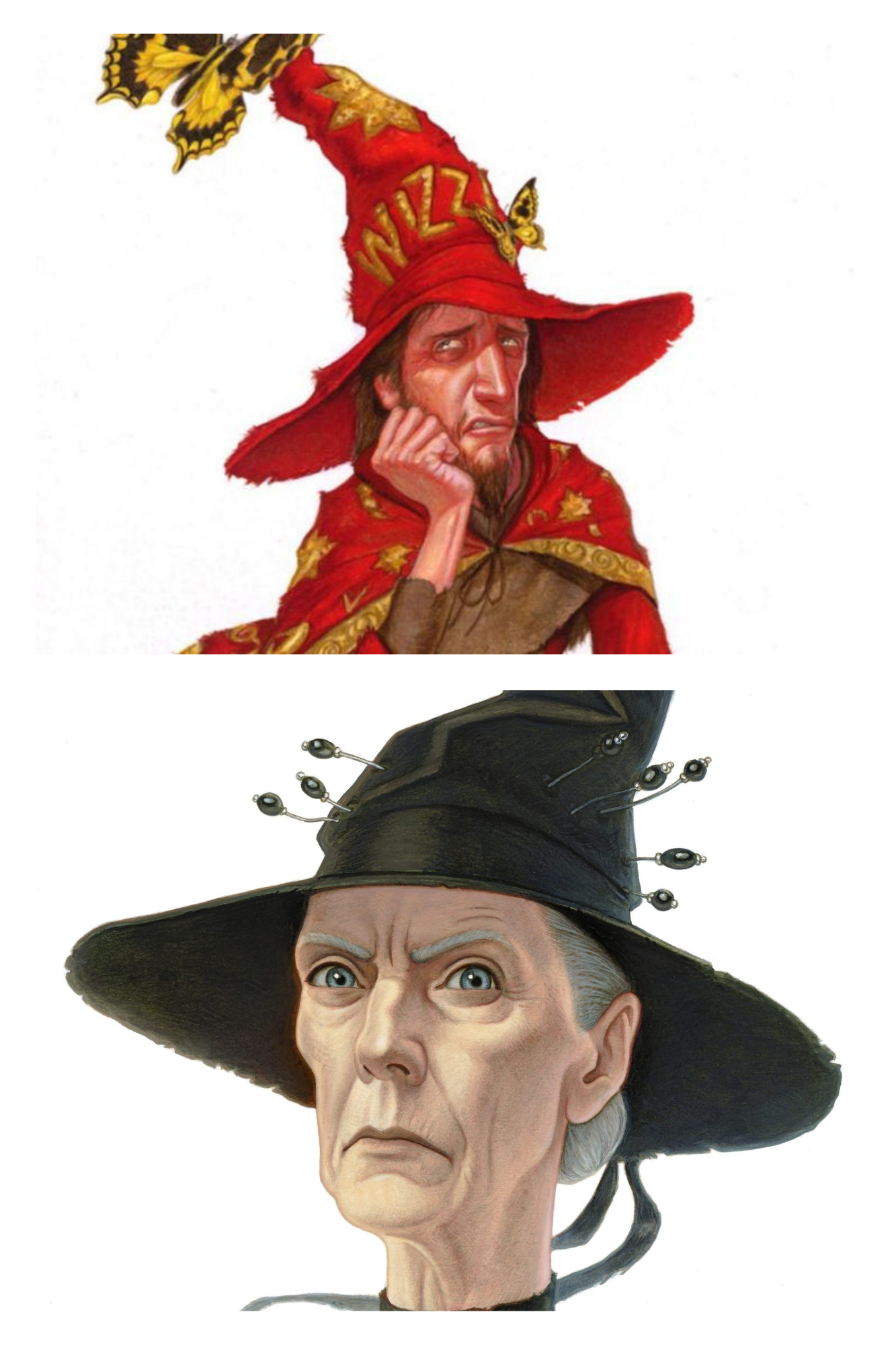


Rincewind and Granny Weatherwax, Death and Great A’tuin
It’s at this point where I had my first stroke brainwave and remembered something I’d seen a few years back. A central part of ‘Going Postal’, one of my favourite books, was the clacks network, a series of semaphore towers that would transmit messages between points. For various spoiler-y reasons, sending the clacks message “GNU Terry Pratchett” became a sort of tribute, with the message even making it onto the web. A nice idea, very fitting given the story of the books.
Remember criteria 3 from earlier?
Nothing crazy
I decided that I was going to create an ESP32-based BLE mesh that would function exactly like the clacks and would pass messages from one badge to the next. You’d be able to send your own messages via the I2C connection to the Pi and read them on a little screen on the front. Then I had another stroke great idea and decided I was going to put little vibration motors on all the badges, and they’d vibrate just like the clacks panels in the book to indicate messages and everyone was going to be talking to each other using the clacks and it was going to be amazing.
I can’t really remember at what point I realised that this was all a terrible idea, but I suspect it was around the same time I worked out what it would actually cost to buy enough ESP32’s for all of the badges (which incidentally was almost as much as what the final boards ended up costing without them). Unfortunately, I’d already spent several days planning out how I was going to do all of this, by which time there was just over a month to go before Berlin. So, I went back to the drawing board and came up with a much simpler design.
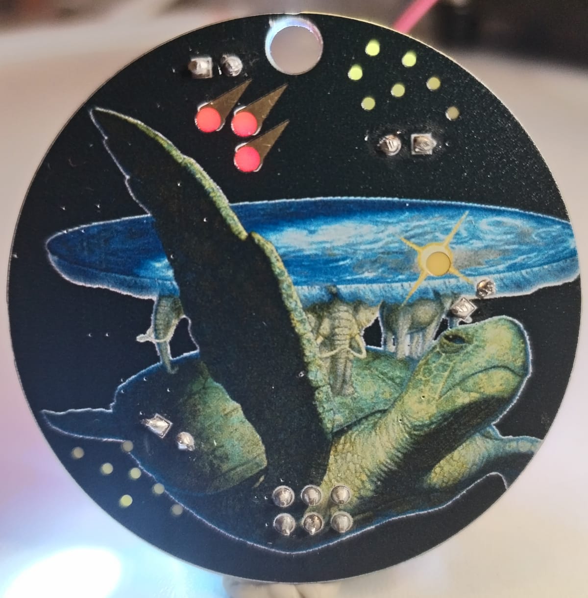
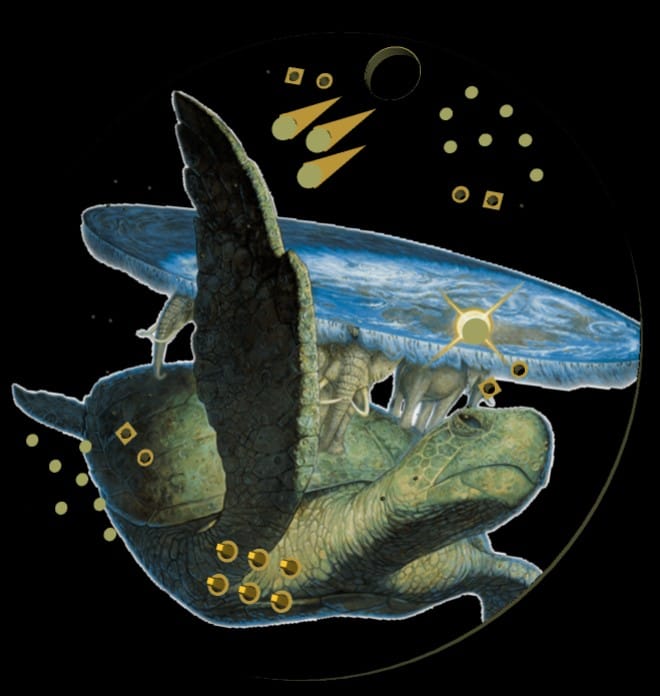
The general idea was to get the art onto the PCB using JLC's colour silkscreen process [[4]]. I decided to have five different transparent areas on the PCB. Since A’tuin is flying through space, I decided on three different patches of white stars around them that would fade in and out, to try and achieve a twinkling effect. The sun travelling around them would get a yellow LED and I decided to add three copper meteorites that would have a red LED behind them
[[4]]: In order to get this service you'll need to use EasyEDA Pro. Weirdly the pro version doesn't seem to have community footprints available, hence why the majority of this project was done in the basic EasyEDA version.
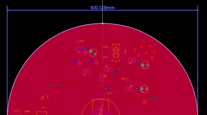
Since I've never done a board with transparent areas on the PCB, I decided to do a quick test board to double check this before committing to the final badge.
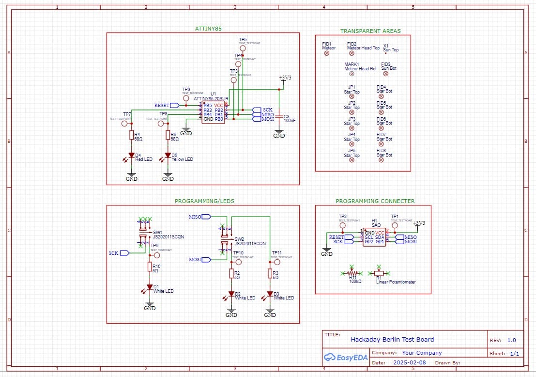
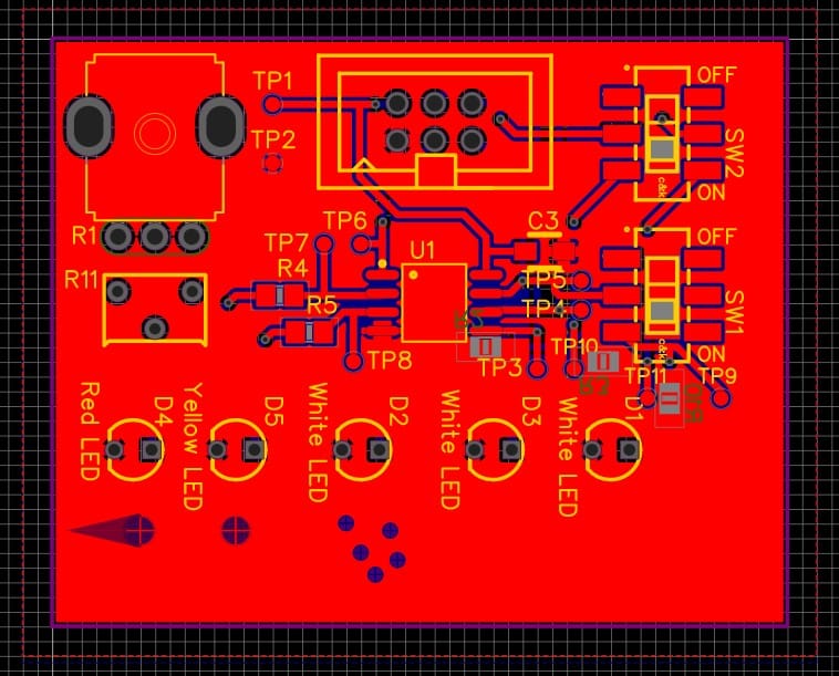
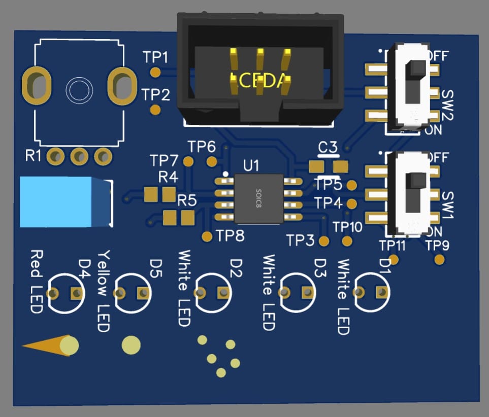
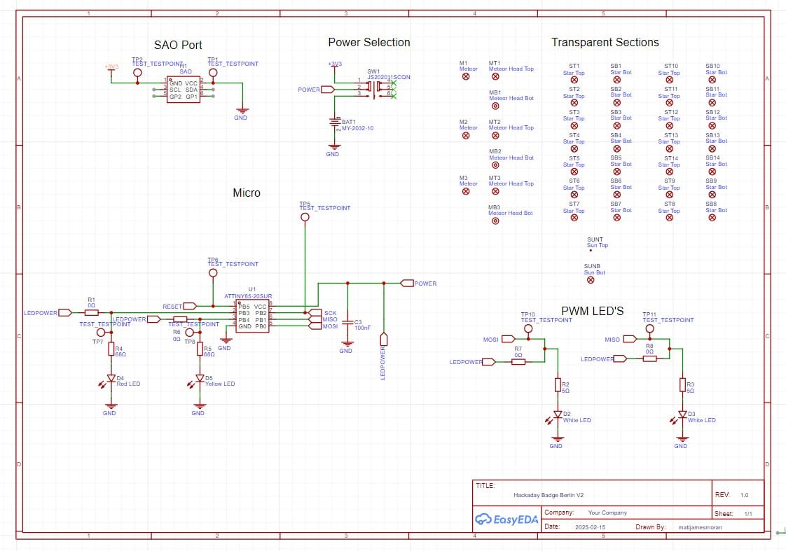
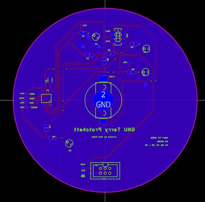
Schematic and PCB for the test board. The bottom left of the PCB shows the copper meteor, the sun and the patch of stars. The two potentiometers in the top left were for a different project as I wanted to double check their footprints were correct.
The circuit was built around an ATTiny85. This was partly due to the price but was mostly because it can be programmed via an Arduino using Arduino code. This helped me avoid doing any real programming sped things up so I could focus on the hardware. Since we've only got 8 pins on the micro to work with in total, to avoid constantly resoldering components I added switches to flip the pins connections between the programmer and the LED's. I also didn't want lots of holes in the artwork on the badge, so the majority of components are SMD.
The main exception to this was going with through-hole LED's instead of surface mount ones. The logic here was that since apart from the sun, all of the transparent areas would be groups of small circles. In theory, you could use a single through hole LED to shine through a bunch of areas and not need to use a few SMD LED's [[5]].
[[5]]: In practise this turned out to be a terrible idea but we'll get to that later.
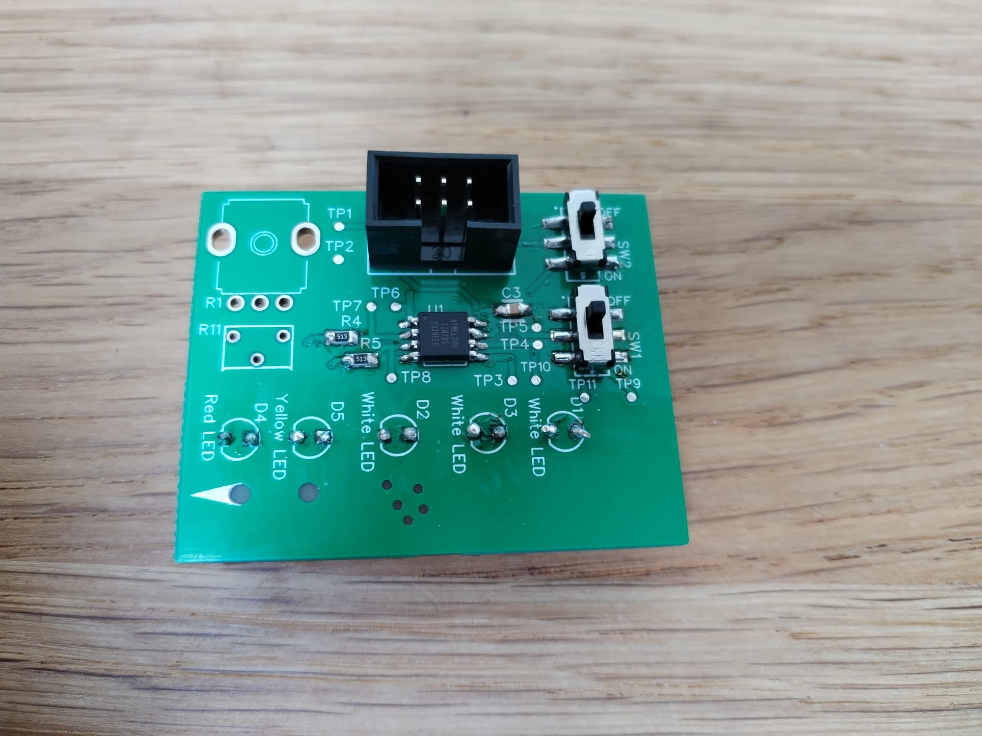
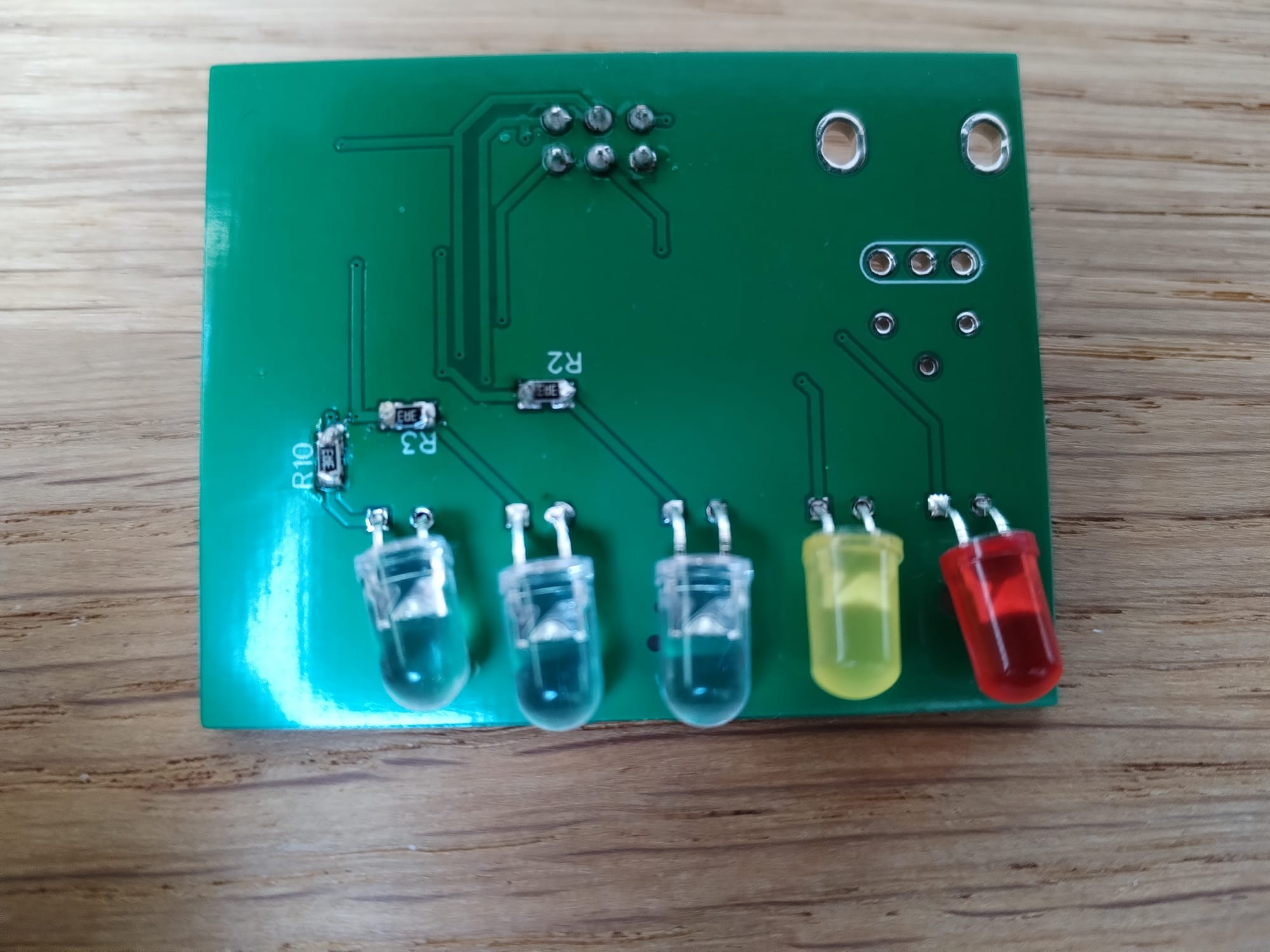
The components arrived about the same time as the boards so were assembled relatively quickly. A few teething problems with programming later...
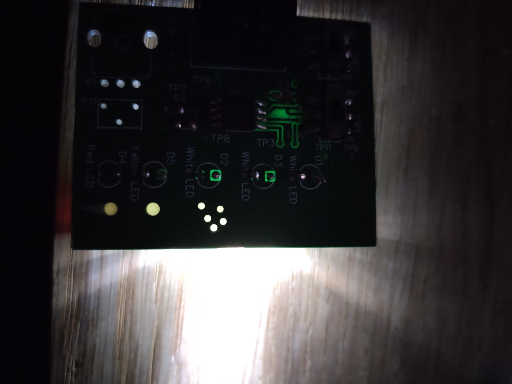
Overall a success-the transparent bits are lit up and the fade effect for the white LED's worked well. Originally I had planned for three white LED's to fade in and out one at a time, but went with just two after having some difficulties with the PWM [[6]].
[[6]]: The ATTINY technically only has two PWM channels but there are four pins they can output to. In theory you should be able to swap which pin each channel is writing to via manipulating the registers but I didn't have the time to fully investigate this.
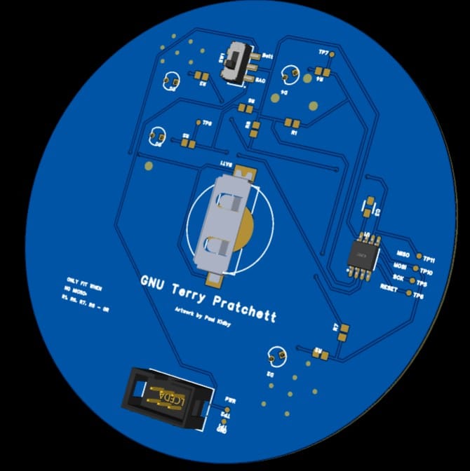
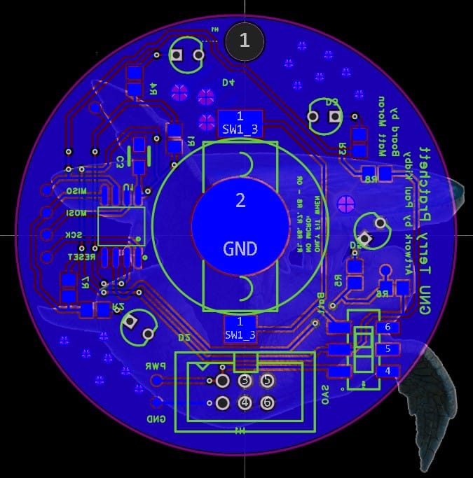
Following this I went ahead with the final badge. There were a few changes to make for this. The main one was adding a coin cell holder for an alternative power source. Its not quite as good as powering the board via the SAO port - standard coin cells are usually just 3V rather than the badges 3.3V. However its good enough for showing it to people. Since the microcontroller is the most expensive part of the board, I also added zero ohm links to power the LEDs for boards without it fitted [[7]]. Finally, a lot more care was taken with the PCB layout - I wasn't sure how obvious the traces would be underneath the art so tried to keep everything to the bottom side of the board.
[[7]]: This was surprisingly difficult since EasyEDA doesn't have a built-in non fit option. I ended up having to do the entire schematic and PCB without them, running the ERC and correcting any issues, then adding them back in and ignoring the warnings about sharing nets.
With just two weeks to go until the event, I had a fully done schematic and board layout. All that was left to do was order the boards. Right?
Its at this point where my multiple strokes started to catch up with me. For example, observant readers may have noticed something odd about the schematic above.
Hmm.
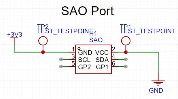
Just before ordering, I thought it might be a good idea to double check there wasn't anything I was missing. While reading the Hackaday.io page about SAO's I noticed something odd.
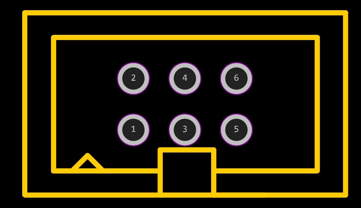
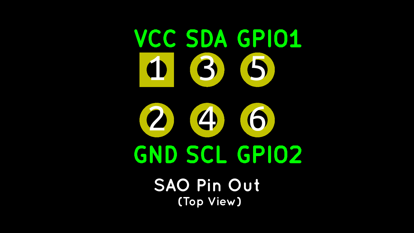
Community footprint vs Hackaday footprint
The SAO port footprint available on the EasyEDA library was reversed, which is what happens when you blindly trust strangers on the internet. Luckily since I wasn't using any of the other pins for my board, it was a quick job to just swap around the power and ground.
Since I'd already burned myself once by not looking at any SAO info, I decided to have a quick look online for anything else I'd missed. While reading an article about creating a jolly wrencher SAO, one line stood out.
the badge size was about 8 cm x 8 cm – too large for an average SAO, and definitely too large compared to the Supercon badge.
Hmm.
Somehow while looking at all the other SAO badges I'd never gotten an idea of how small they actually are. My badge was double the size of what the articles badge ended up being.
After cutting the size down to an 5 cm diameter circle, one stressful evening later I finally had a working PCB design.
With Berlin a couple of weeks away I put in the JLC order and ordered the parts.
One week later...

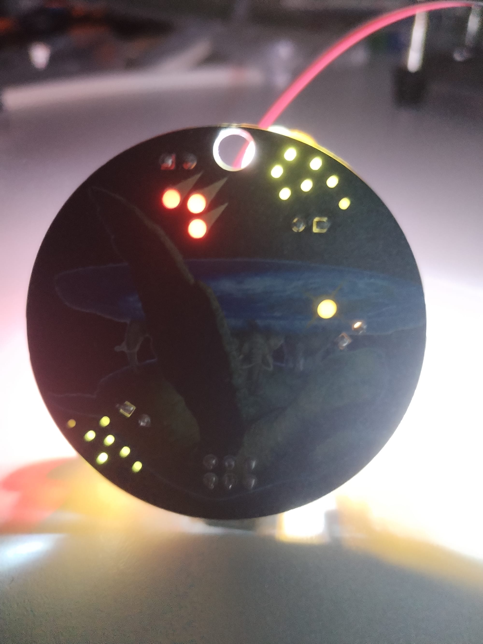
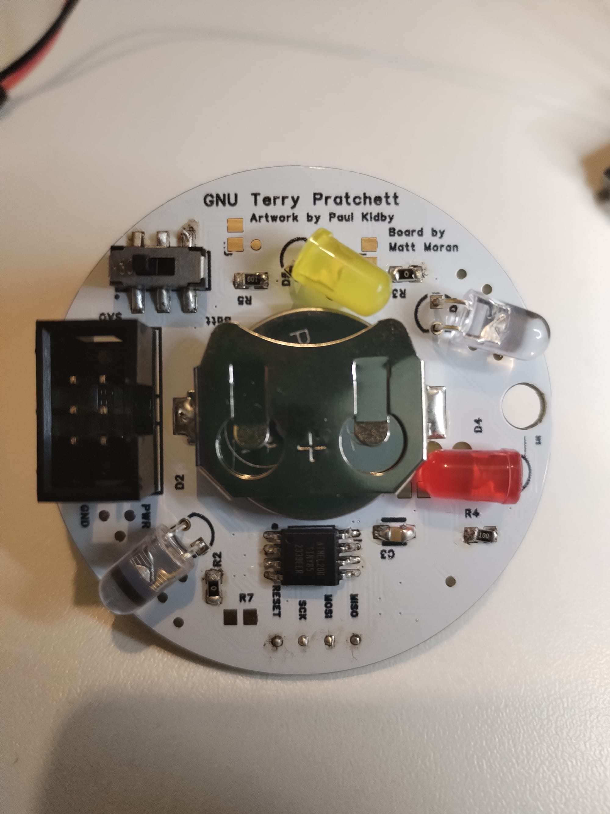
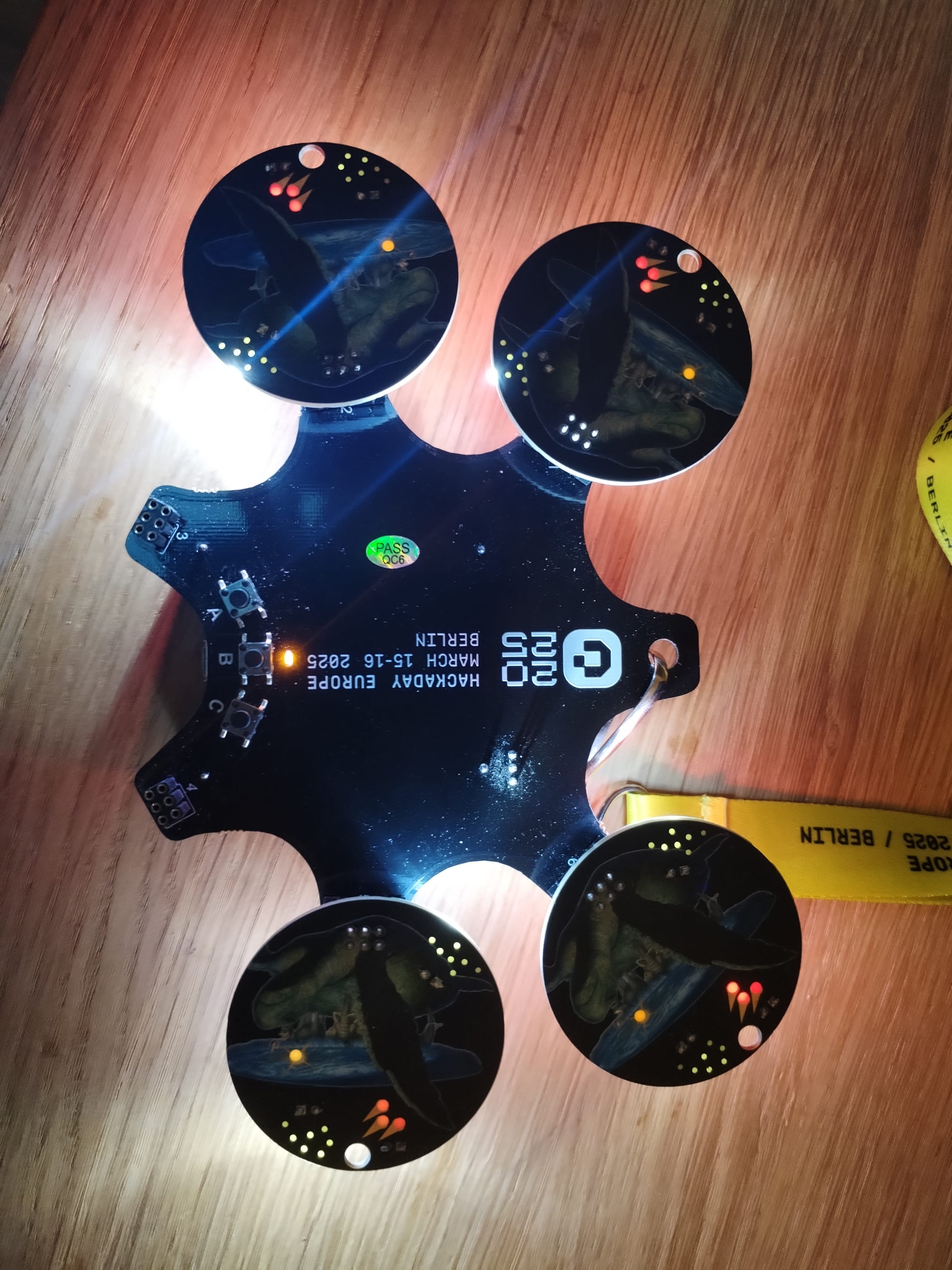
Not too bad! The art turned out great and the boards seemed decent quality - the silkscreen was legible and all the transparent areas were fine. I ended up assembling about 12 in various states. Since I wanted a few left to give to other people I split them up between just SAO ports and just battery holders. Additionally there were a few lacking micros since I was trying to keep the cost down.
Unfortunately during assembly I realised there were a few other problems. For one, the yellow LED blocks the coin cell holder, which means the battery has to be inserted before soldering the rest. I haven't done a proper current measurement yet for the board so fingers crossed I won't need to worry about this for a while. I also had some issues programming-I'd planned to just press a 4 pin header connected to the Arduino onto the badge's programming test points but sadly this didn't consistently work across the different boards. For future boards I'll likely invest in some spring loaded pins but for this I had to spend a lot of time soldering and de-soldering the pin headers[[8]].
[[8]]: Top tip: Don't do what I did and try and save space by having test points in line with the trace rather than coming off to the side. When I accidently lifted the test point pad while de-soldering the header, it broke the trace and meant I had a board with only one white LED working.
Eventually I managed to actually get to Berlin and found a fun final problem - because I'd had to make the LED's bright enough to shine through the PCB, when not viewing from the front the badge was like staring into the sun.
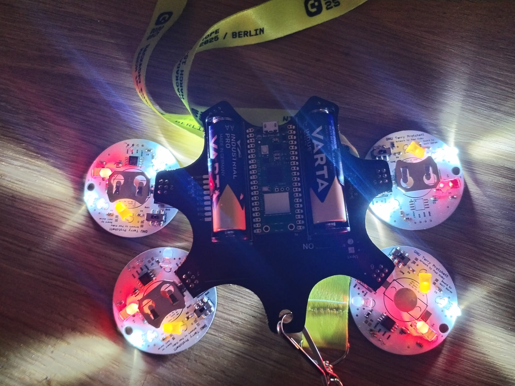
Overall though I'm happy with how the project turned out. I'm planning to write a quick post about the conference itself but in general it was a good time! Hopefully I'll be back next year with a new badge that won't blind other attendee's or confuse German's who've never heard of Discworld.